Sheet stamping parts are very common in aerospace engines and their role is very important. Fluorescent penetrant testing is often used in the manufacturing process to ensure the surface quality of the parts.
When the stamped parts of the sheet are inspected by fluorescence permeation, if there is excessive fluorescence background (the surface of the part has bright yellow-green fluorescence), the contrast between the fluorescent trace display and the defect-free background at the defect will be reduced, making the human eye It is difficult to identify defects, and in severe cases, the defects cannot be detected. Chou Meigan of SCOUT UVLED analyzes the cause of excessive fluorescent background and formulates pre-process testing methods.
1. Problem Description
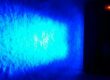
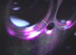
The surface of the stamping parts of the sheet is in a dry sandblasting state with high roughness. After the fluorescence permeation detection treatment, all the surfaces under the black light show a uniform yellow-green fluorescent background, as shown in Fig. 1. Some surfaces exhibit a uniform yellow-green fluorescent background, as shown in the yellow-green fluorescent area on the right side of Figure 1. After the background is wiped, the metallic base is exposed as shown in Figure 1, and the purple-blue area on the left side. After re-infiltration, it will once again show a yellow-green fluorescent background phenomenon.
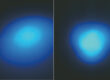
The batch of parts was observed under white light, and there was no abnormality on the surface of the part, as shown in Figure 2.

1. Excessive yellow-green fluorescent background on the surface of parts under ndt black light

2. No abnormalities were found on the surface of the part under white light
2. Causes
2.1 Physical and Chemical Analysis
In order to analyze the cause of the formation of excessive fluorescent background, a part of the batch was randomly selected for physical and chemical analysis. The analysis report concluded that the surface roughness of the part is high and the surface has residual varnish.
2.2 Process Test
2.2.1 The following factors are considered from the influencing factors derived from physical and chemical analysis.
(1) From the aspect of surface roughness, the surface roughness of the batch of parts is almost the same as the surface roughness of other batch parts of the part number, and there is no excessive background of fluorescent background.
(2) As a loose medium, the varnish is easy to adsorb the fluorescent permeate and form a yellow-green fluorescent background. Under normal situations, the varnish can be completely removed from the surface of the smooth part by using an organic solvent such as acetone. That is, re-penetrated after being erased to obtain a background conforming to the fluorescence permeation detection.
According to the above analysis, if any of the above two factors exist on the surface of the part, after the parts are processed by the normal pre-cleaning process, there will be no excessive fluorescent background; if the part has excessive fluorescent background, it should be a combination of two factors. the result of.
2.2.2 Penetrant Testing Process
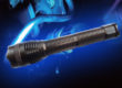
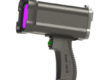
The part was subjected to a dipping method to apply a fluorescent permeate, and the permeation time was 15 min (in which 7 min was immersed and dripped for 8 min). The excess permeate was removed by manual cleaning. The drying temperature was not higher than 70 °C, and the drying time was 10 min. The image was developed with a dry powder imaging agent, and the imaging time was 10 min to 4 h. The UV intensity of the ndt black light is suggested larger than 1200 uW/cm². Here we are using S3120-4K ndt black light for penetrant testing.

2.2.3 Test Verification
(1) Test #1
The infiltration treatment is completed in one of the other batches of the part as specified in Section 2.2.2 (see Figure 3). Observe the surface of the part under the ndt black light to verify that the roughness of the surface of the part will cause excessive fluorescent background when there is no residual varnish. Figure 4 shows that the surface roughness of the part does not cause excessive fluorescence background.

3. Penetrant Testing Process

4. Under the NDT black light after PT process
(2) Test #2
It is used to verify that when the surface roughness of the part is high, the varnish is completely removed from the surface of the part and re-infiltrated with an organic solvent such as acetone, and an excessive fluorescent background is not formed again.
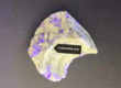
Apply a varnish to the surface of a smooth metal plate and dry it naturally in air to make a test plate. Complete the permeation treatment according to the requirements in Section 2.2.2 to obtain the results shown in Figure 5. Then test the plate with organic solvent acetone. The surface of the varnish is erased. Finally, the test plate is re-infiltrated according to the requirements in 2.2.2, and the surface of the test plate is observed under a black light, as shown in Fig. 6.

5. Varnish adsorbs fluorescent permeate to form a background

6. Wipe the varnish after re-infiltration treatment
Figure 5 shows that the varnish is a loose medium that readily adsorbs the fluorescent permeate and forms a yellow-green background. Figure 6 shows that the varnish can be completely removed from the smooth surface of the part by using an organic solvent such as acetone.
(3) Test #3
It is used to verify that when the surface roughness of the part is high, after the varnish is washed with an organic solvent, the re-permeation treatment still gives an excessive fluorescent background.
Apply a surface of acrylic acid varnish to the surface of the part that meets the requirements (Note: parts selected from batches that do not have excessive fluorescent background), and dry it naturally in air to make the test piece.
The infiltration treatment was completed as required in Section 2.2.2 to obtain the results shown in Figure 7. The varnish on the surface of the test piece was then removed using an organic solvent acetone to obtain the results shown in Figure 8. Finally, the test piece is re-infiltrated according to the requirements in Section 2.2.2, and the surface of the test plate is observed under the ndt black light, as shown in Fig. 9.

7. Varnished test piece for Penetrant Testing

8. Wipe with acetone

9. Re-infiltrated test piece on yellow-green background under ndt black light
As can be seen from Figure 9, the test piece appears to have the same background over the yellow-green background in Figure 1.
2.3 Conclusion
The results of the process test verified that the varnish was prone to remain when the surface roughness of the part was high, and the varnish adsorbed the fluorescent permeate to form an excessive fluorescent background.
Combined with the conclusion of physical and chemical analysis, it is concluded that the over-background problem of the batch parts is caused by the excessive fluorescing background of the residual varnish adsorbing fluorescent permeate on the rough surface of the part.
3. Pretreatment Method Before Permeation Detection Of Excessive Fluorescent Background
The pretreatment methods that can be used before the penetrant test generally have the following types: 1) Solvent cleaning. 2) Chemical cleaning. 3) Mechanical cleaning.
For the three methods, the following tests were performed:
3.1 Solvent cleaning
After the fluorescent parts of the batch appeared excessively, the whole batch of parts was cleaned by ultrasonic cleaning machine combined with acetone cleaning (washing time was 10, 15, 20 min respectively), and each cleaning was as required in section 2.2.2. Re-infiltration treatment, the results obtained is no improvement in background. The results show that solvent cleaning can not effectively remove the residual varnish on the rough surface of the part.
3.2 Chemical cleaning
As a method of removing the surface paint layer, chemical cleaning needs to establish and strictly control the cleaning time according to the specific conditions of the surface paint layer of the part to prevent the chemical solution from damaging the parts. The varnish remaining on the surface of the batch part cannot be directly observed by the naked eye. Therefore, the degree of varnish residue on the surface of the part cannot be determined, and the residual degree of varnish on the surface of the part is different. Therefore, when the chemical cleaning method is selected, the formulation of the parameters is difficult and the operability is poor.
3.3 Mechanical cleaning
There are many methods for mechanical cleaning. The factory usually uses sanding and sand blowing methods. The sanding and sand blowing methods can be subdivided into various methods.
The surface of the test piece with excessive background is treated by mechanical cleaning. After treatment, it is re-infiltrated as required in Section 2.2.2. The results are shown in Figure 10 to 12.

10. Fine abrasive cloth polishing surface

11. Polish the surface with a sharpening knife

12. Wet blowing
4. Summary
The Cause for the excessive background of fluorescent background on the surface of the batch is that the surface varnish of the part with high roughness is easy to remain, and the residual varnish absorbs the fluorescent permeate, forming a fluorescent background which is difficult to remove by common cleaning methods.
In view of the excessive fluorescence background of the parts, the factory can use wet sandblasting and sanding as a pretreatment method for fluorescence penetration detection. Practice has shown that: the selected mesh paper and the tip of the blade should be as large as possible to ensure the grinding. The removal margin is small and the polished surface is smooth and flat, avoiding the formation of an excessively rough surface, and again adsorbing the fluorescent permeate to form an excessive background.
– Adapted from《Nondestructive Testing》 #2. Vol.38. 2016