Aviation duct connection clamps are widely used in aircraft and their quality directly affects the flight safety of the aircraft. During regular aircraft overhaul, it is necessary to conduct relevant non-destructive testing on the aviation duct connection clamps. The disassembled clamps were ultrasonically surface cleaned and then inspected for surface quality using fluorescent penetrant testing. The results show that after the identification of true and false defects, defects such as open cracks on the surface can be effectively detected, ensuring the safety of the aviation duct connection clamps.
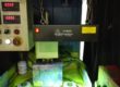
Piping system is an important system for aircraft to transport liquid. It plays an important role in the connection and fixation of aircraft pipeline, and has the characteristics of high temperature resistance, high pressure resistance, corrosion resistance, high sealing and high reliability. During the flight of the aircraft, the clamps are easily damaged under high temperature, impact load and resonance, as shown in Figure 1, which leads to oil and gas leakage and affects the flight safety of the aircraft. During the regular overhaul of the aircraft, it is necessary to conduct relevant non-destructive testing on its duct connection clamps. After ultrasonic surface cleaning of the disassembled clamps, defects such as surface opening cracks can be effectively found.

Fig.1 Fracture damage profile of aviation conduit connecting clamps
At present, a type of aircraft used in the third generation of the conduit connection clamps (HB6521), as shown in Figure 2, where 1 for the band, 2 for the bolt, 3 for the nut, 4 for the file, 5 for the rivet, 6 for the bushing. The material of the clamps, circlips, bushings, gears and bolt bushings is 2Cr13Ni4Mn9 steel, of which the thickness of circlips, bushings and gears is 1.5 mm and the thickness of bolt bushings is 1.2 mm. 2 rigid flanges are made of 5A02 rustproof aluminum, and the thickness of flanges is 1.5 mm.
The thickness of the bushing is 1.0 mm, the diameter of the bolt is 6 mm, and the head size is 16 mm. According to the material and structure of the conduit clamp itself and the characteristics of the defects produced mainly by surface open cracks, the water-washing type fluorescent penetrant testing method is selected to meet the testing requirements.

Fig.2 Conduit connection clamp structure diagram
Catheter clamps work in harsh environments for long periods of time and require surface preparation prior to fluorescent penetrant testing. Solid contaminants, such as grease, oxide, etc., are removed from the clamp surface. Pre-cleaning uses ultrasonic cleaning with cleaning agents to remove mainly liquid contaminants on the surface of the inspected clamps as well as solid particles encapsulated by oil and dirt. Any contaminants that may affect penetration detection must be removed. At the same time, the clamp must not be damaged. If the pre-cleaning liquid enters the surface opening defects, the penetrating liquid cannot enter the surface opening defects, forming the wetting and blocking phenomenon, so the clamp must be thoroughly dried after pre-cleaning to prevent the wetting and blocking phenomenon.
Using the dip-coating method to apply a water-washed fluorescent infiltration solution to the clamps, i.e., the inspected clamps are placed in a wire basket and all immersed in the infiltration solution. This method of full penetration, fast penetration speed, high efficiency, suitable for use in a large number of clamps in a comprehensive inspection. The infiltration temperature range is generally from 15 to 50 ℃, and the infiltration time range is generally from 10 to 30 min. In the actual inspection process, the plant temperature is generally 15°C, and the actual infiltration time is set to 15 min. At the end of the infiltration process, the clamps need to be dripped to reduce the loss of infiltration solution.
Water washing is to remove the excess penetrant on the inner and outer surfaces of the inspected clamp without cleaning the penetrant that has penetrated into the defect. During the cleaning operation, spray mist water column at about 25°C, and the water pressure is not higher than 0.27 MPa. The cleaning operation is monitored under a black light. The water-washing permeate contains emulsifier, so if the washing time is too long, the washing temperature is too high, and the water pressure is too high, the permeate in the defect may be washed away, resulting in over-cleaning.

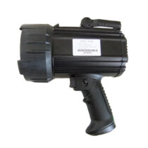
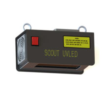
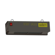
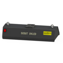
Fig.3 Overhead UV lamp
The drying process is to remove the moisture from the surface of the inspected clamps, especially to blow dry the moisture in some connection gaps and thread roots. Since water cleaning and dry powder imaging are used, the drying process must be carried out before the image is developed. After water cleaning, first wipe off the obvious moisture on the surface with medical gauze, then blow off the moisture on the inside and outside surfaces of the clamps with clean compressed air, especially the moisture in the connection gap and the root of the threads that may accumulate water, and finally put them into the hot air circulation drying cabinet, with the drying temperature set at 50 ℃ and the time at 4 min.
At the end of drying, immediately put the inspected clamps into the powder spraying cabinet for powder spraying image. If the image time is too long will cause the defect display is overly magnified, so that the defect display distortion, reduce the resolution. If the image time is too short, the permeate within the defect has not been adsorbed to form the defect display, resulting in defect leakage. So, in the actual detection, the image time is set to 15min.
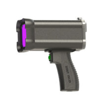
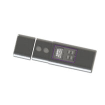
The inspection shall be carried out at the end of the display, and the display shall be judged as true or false; the display judged as defective shall be marked with location and size. The inspection shall be carried out in a dark room and under an UV-A lamp like Firgue 4 shows. The UV intensity of the examined clamp surface shall be not less than 1000 uW/cm², while the visible light intensity in the dark room shall not exceed 20 lux.

Fig.4 Portable UV-A Lamp
After the inspection, there is a residual image developer and a small amount of permeate on the internal and external surfaces of the clamp. In order not to affect the subsequent assembly and the use of the inspected clamp, the residue is removed by ultrasonic solvent (at least 3 min).
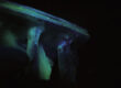
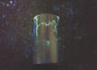
Due to the long-term working of aviation conduit connection clamps in harsh environments, the internal and external surfaces of the clamps are prone to scratch and bump marks, thus forming a false display during fluorescent penetrant testing. In the inspection of the clamp, the true and false defect display must be effectively identified. The specific identification method is as follows: use a medical gauze (not saturated and wet) with a small amount of alcohol, gently wipe the defect display along the same direction, gently blow dry the residual alcohol on the surface after wiping to make it evaporate quickly, if the defect display disappears and no longer appears, the defect display is a pseudo display, and the scratch or bump marks are generally visible under white light with a magnifying glass, as shown in Figure 5; if the defect display disappears after wiping, and then slowly appears again, the defect display is a pseudo display. disappears, and then slowly appear, this defect display for the true display, as shown in Figure 6 display process.

Fig.5 Scratch marks

Fig.6 The display process after true defect rechecking
Fluorescent penetrant testing of multiple batches of clamps was conducted for multiple sorties, and it was found that cracks were easily shown at multiple locations in the clamps, as shown in Figure 7. According to the long-term experience of fluorescent penetrant testing of aviation conduit connecting clamps, the welding point is the defect-prone area during the inspection because of the thin thickness of the clamps and the special material, and the welding difficulty. The end of the clamp, the bolt, the inside and outside of the ring and its R angle are the key areas of force, so they should also be checked during the inspection.

Fig.7 Crack display in different parts of the clamp
The fluorescent penetrant testing method was used to inspect multiple batches of clamps in multiple sorties. Through the effective identification of genuine and false defects, it was found that certain specific parts of the clamps are prone to surface open crack defects. The penetration inspection method has accumulated experience for the future nondestructive inspection of clamps, while ensuring the safe flight of the aircraft.